| Table of Contents |
Crummett and Western, Physics: Models and Applications,
Sec. 27.1,2,3
Halliday, Resnick, and Walker, Fundamentals of Physics (5th
ed.), Sec. 27-4,5; 28-3,4,5,6
Tipler, Physics for Scientists and Engineers (3rd ed.), Sec.
22-2, 23-1
The most basic electrical property of matter is resistance. The electrical resistance of a piece of material determines its behavior in a DC circuit. (Other properties must also be considered in circuits in which signals vary with time.) A material whose resistance is independent of the current in it obeys Ohm's law:
![]() (1)
(1)
where the resistance R is a constant. In (1), V is the potential difference across R, and I is the current through it.
 The behavior
of resistances and voltage sources connected in complex circuits can be
analyzed by Kirchhoff's laws. The first of these, the junction theorem,
expresses the fact that electric charge is conserved:
The behavior
of resistances and voltage sources connected in complex circuits can be
analyzed by Kirchhoff's laws. The first of these, the junction theorem,
expresses the fact that electric charge is conserved:

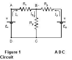
For example, in the circuit in Figure 1, currents I1 and I2 flow toward point B, while current I3 flows away from B. Therefore
![]()
Kirchhoff's second rule, the loop theorem, expresses the fact that the potential at any point in a steady-state circuit has a definite value:

In Figure 1, as an example, consider path ABCD. Starting at A, we first
encounter a potential drop I1R1 (by Ohm's
law) in resistor R1, then another drop I3R3
in resistor R3, and finally a potential increase of amount
![]() as we pass through the emf from negative to positive. Thus
as we pass through the emf from negative to positive. Thus
![]()
or![]()
If we know the emf's and resistances in a circuit, Kirchhoff's two laws always provide exactly enough independent equations to solve for all the branch currents.
The familiar rules for series and parallel combinations of resistances follow from these ideas. If two resistances R1 and R2 are connected in series, the voltage drop V across the combination is the sum of the voltage drops across each, while the same current is flowing in each:
![]()
or
![]() (2)
(2)
If the two resistors are connected in parallel, on the other hand, the potential difference across each is the same, but the current divides; the total current is the sum of the two individual currents:
or
 (3)
(3)
In this experiment, you'll check the application of Ohm's law, the formula (3) for parallel combination of resistances, Kirchhoff's laws, and (if there is time) the superposition theorem of elementary network theory, in some simple circuits.
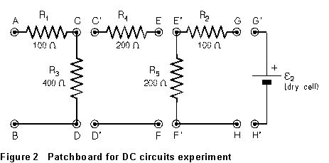
The circuit of the "patchboard" is shown in Figure 2. By making
different connections on it, you can set up several different simple circuits.
In this experiment, you'll make current measurements by measuring the voltage
drop across precision resistors, using a digital voltmeter. In the circuit
of Figure 2, 200 ![]() ,
1% tolerance resistors were used in making the patchboards; "tolerance"
is several standard deviations, so you can consider that each of the resistance
values has a standard deviation of around 0.3%. Using the voltage drop
across the resistor for current measurement is thus much more accurate
than direct measurement with an analogue meter would be, so you'll determine
currents just by measuring the voltage drop across the known resistors.
,
1% tolerance resistors were used in making the patchboards; "tolerance"
is several standard deviations, so you can consider that each of the resistance
values has a standard deviation of around 0.3%. Using the voltage drop
across the resistor for current measurement is thus much more accurate
than direct measurement with an analogue meter would be, so you'll determine
currents just by measuring the voltage drop across the known resistors.
In applying Ohm's and Kirchhoff's rules, keep the following conventions in mind:
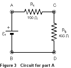 (1) Arrange
the circuit as shown in Fig. 3, using the DC power supply as voltage source
(1) Arrange
the circuit as shown in Fig. 3, using the DC power supply as voltage source
![]() .
(The positive terminal of the power supply is red, the negative terminal
black.) Set your digital meter to the 10 V DC scale, and connect it from
point A (+) to point B (-), so that it measures the output voltage of the
power supply. Turn on the power supply and adjust the voltage controls
(coarse and fine) until the voltage reads 5.00 V. Leave the controls at
this position for the remainder of the experiment. Now disconnect the digital
voltmeter from A and B without changing anything else in the circuit.
.
(The positive terminal of the power supply is red, the negative terminal
black.) Set your digital meter to the 10 V DC scale, and connect it from
point A (+) to point B (-), so that it measures the output voltage of the
power supply. Turn on the power supply and adjust the voltage controls
(coarse and fine) until the voltage reads 5.00 V. Leave the controls at
this position for the remainder of the experiment. Now disconnect the digital
voltmeter from A and B without changing anything else in the circuit.
(2) Measure and record VAC. Calculate the current in R1 from your measured value of VAC and the known value of R1 (100 ohms).
(3) Measure the potential difference VCD between points C and D. Knowing that the current you calculated in step 1 is also the current in R3, calculate the resistance of R3.
(4) Measure VAD. Compare this value with the sum of VAC and VCD measured in steps 2 and 3. Calculate the percentage difference between these two values. How do they compare? Is the difference reasonable in light of your measurement uncertainties?
(5) Turn off the power supply. It is possible, by connecting certain points of the patch board and connecting the power supply to appropriate points, to achieve a circuit just like that of Fig. 3 except that resistor R4 is located in the position occupied by R3 in the figure. Diagram this, showing which points of the patch board you connected to achieve the desired circuit. Wire up the circuit, double-check it, turn the power supply on, and repeat the procedure of steps (l) through (4). Determine the value of R4.
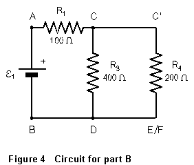 (6) Connect
the variable DC power supply between points A (+) and B. Make the circuit
shown in Figure 4, with resistors R3 and R4
connected in parallel.
(6) Connect
the variable DC power supply between points A (+) and B. Make the circuit
shown in Figure 4, with resistors R3 and R4
connected in parallel.
(7) Connect the DVM between points A and B. Turn on the power
supply and set the supply voltage ![]() = 5.00 V. Measure the potential drop from A to C, and from C to D. Using
the known value of 100
= 5.00 V. Measure the potential drop from A to C, and from C to D. Using
the known value of 100 ![]() for R1, calculate from VAC the current
being provided by the power supply. This current flows through the parallel
combination of R3 and R4 and returns
to the supply. The effective resistance of the parallel combination can
therefore be found from
for R1, calculate from VAC the current
being provided by the power supply. This current flows through the parallel
combination of R3 and R4 and returns
to the supply. The effective resistance of the parallel combination can
therefore be found from

Calculate this value. It should agree with what you calculate from Equation
(3), using the known values of R3 = 400 ![]() and R4 = 200
and R4 = 200 ![]() ,
within experimental error. Does it?
,
within experimental error. Does it?
 (8) Turn
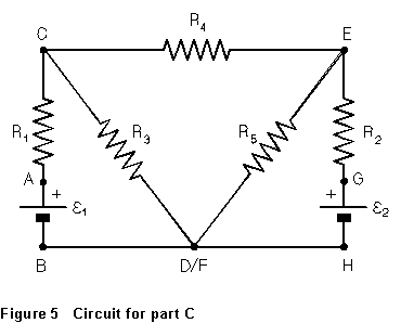
off the power supply. On the patchboard, wire up the circuit shown in Figure
5. The variable DC power supply is
(8) Turn
off the power supply. On the patchboard, wire up the circuit shown in Figure
5. The variable DC power supply is ![]() ,
while the dry cell mounted on the patchboard is
,
while the dry cell mounted on the patchboard is ![]() .
Connect the DVM between A and B, and adjust the power supply for a reading
of exactly 5.00 V.
.
Connect the DVM between A and B, and adjust the power supply for a reading
of exactly 5.00 V.
(9) Without changing the supply voltage, measure directly the
terminal voltage ![]() of the dry cell in the circuit. Next, measure and record the potential
drop across each of the five resistors, with sign. Calculate the current
in each of the five resistors. Figure out and record the direction of the
current in each branch of the circuit (remember that current flows through
a resistance from the higher to the lower potential). At each of the circuit's
three junctions (C, E, and D/F), add the currents flowing into the junction.
(Add them with sign; that is, a current flowing away from the junction
is taken as negative.) Do the currents add to zero (within experimental
error), as they should according to Kirchhoff's first rule?
of the dry cell in the circuit. Next, measure and record the potential
drop across each of the five resistors, with sign. Calculate the current
in each of the five resistors. Figure out and record the direction of the
current in each branch of the circuit (remember that current flows through
a resistance from the higher to the lower potential). At each of the circuit's
three junctions (C, E, and D/F), add the currents flowing into the junction.
(Add them with sign; that is, a current flowing away from the junction
is taken as negative.) Do the currents add to zero (within experimental
error), as they should according to Kirchhoff's first rule?
(10) Look at the loop B-A-C-(D/F)-B in the circuit of Figure 5. According to Kirchhoff's second rule,
![]()
that is,
![]()
or
![]()
Remember that the V's have signs! That is, if the potential at point A were lower than that at point C, then VAC would be negative. From your measurements, does the sum (with appropriate signs) of VAC and VCD agree (within experimental error) with VAB?
(11) Repeat step (10) above for the loops G-E-(D/F)-H and C-E- (D/F).
(this part is optional: consult your instructor)
In DC network theory, the superposition theorem states that the
current in any branch of a network containing multiple sources of emf is
the simple sum of the currents that would be produced in that branch
by each of the emf's acting alone. By ![]() (say) "acting alone," we mean with all other emf's set to zero
(that is, short-circuited).
(say) "acting alone," we mean with all other emf's set to zero
(that is, short-circuited).
(12) In step (9), you found the current in each branch of the
circuit of Fig. 5 due to ![]() and
and ![]() together. On the patchboard, disconnect the dry cell from G and H, and
use a lead to connect G and H together. (Do not connect G' and H' together!)
You have now "set
together. On the patchboard, disconnect the dry cell from G and H, and
use a lead to connect G and H together. (Do not connect G' and H' together!)
You have now "set ![]() = 0" and can measure the currents produced by
= 0" and can measure the currents produced by ![]() alone. Use the DVM to measure the voltage drop across each of the five
resistors, and divide by the known resistance values to determine the five
branch currents (with sign) in this case.
alone. Use the DVM to measure the voltage drop across each of the five
resistors, and divide by the known resistance values to determine the five
branch currents (with sign) in this case.
(13) Now disconnect the lead between points G and H, and reconnect
point G to G' and H to H'. Turn off the DC power supply and disconnect
it from points A and B, and use a lead to connect A and B together. You
have now "set ![]() = 0" in the circuit of Figure 5, and can measure the currents due
to
= 0" in the circuit of Figure 5, and can measure the currents due
to ![]() acting alone. Use the DVM to measure the voltage drop across each of the
five resistors, and divide by the known resistance values to determine
the five branch currents (with sign) in this case.
acting alone. Use the DVM to measure the voltage drop across each of the
five resistors, and divide by the known resistance values to determine
the five branch currents (with sign) in this case.
(14) In each of the five branches, the sum (with signs) of the
current due to ![]() alone and that due to
alone and that due to ![]() alone should equal, within experimental error, the total current in that
branch which you measured in part (9). Does it? If not, can you suggest
where the discrepancy might come from?
alone should equal, within experimental error, the total current in that
branch which you measured in part (9). Does it? If not, can you suggest
where the discrepancy might come from?
last update 7/97