| Table of Contents |
Crummett and Western, Physics: Models and Applications,
Sec.11-3,4
Halliday, Resnick, and Walker, Fundamentals of Physics (5th
ed.), Sec. 11-6 to 9
Tipler, Physics for Scientists and Engineers (3rd ed.), Sec.
8-1,2
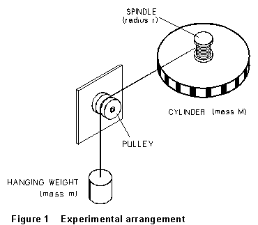
In the apparatus sketched in Figure l, a cylinder is given an angular acceleration by wrapping a string around an attached pulley and hanging a weight from the other end, as shown. The hanging weight is accelerated downward by the force of gravity (opposed by the tension in the string). The other end of the string pulls on the cylindrical surface of the spindle (radius r) and exerts a torque on it which results in the angular acceleration of the cylinder.
By Newton's second law, if the acceleration of the falling mass (m) is a, then
![]() (1)
(1)
where T is the tension in the string.
As the string unwinds, the torques which accelerate the large disk are that due to the string on the spindle, and that due to friction in the pulley and cylinder bearings. Assuming that the moments of inertia of the spindle and pulley are negligible compared to that of the cylinder,
![]() (2)
(2)
where ![]() is the frictional
and
is the frictional
and ![]() the resultant
torque acting on the cylinder, and I is its moment of inertia. r
is the radius of the spindle.
the resultant
torque acting on the cylinder, and I is its moment of inertia. r
is the radius of the spindle.
The linear acceleration (1) of the weight and string is related to the angular acceleration (2) of the cylinder by
![]() (3)
(3)
Solving these for the angular acceleration of the disk gives
![]() (4)
(4)
If we know the mass m of the hanging weight, the moment of inertia
I of the cylinder, the frictional torque ![]() acting
on it (but how do we know this?), and the radius r of the
spindle, then we can calculate the angular acceleration of the cylinder
from Equation (4).
acting
on it (but how do we know this?), and the radius r of the
spindle, then we can calculate the angular acceleration of the cylinder
from Equation (4).
All this, as I said above, as the string unwinds. Now suppose the hanging weight has fallen to the end of the string, hit bottom, "wrapped through," and is moving upward again, rewinding the string on the spindle. The same analysis as above gives for the magnitude of the (negative) angular acceleration
![]() (5)
(5)
(Because now the gravitational and frictional torques are working together
to decelerate the disk). Clearly, if we measure both ![]() and
and
![]() , we can eliminate
, we can eliminate
![]() and so determine I.
and so determine I.
The experiment will be performed using the ROTATIONAL DYNAMICS APPARATUS, a BIB Box input device, and your laptop computer. The cylinder and the pulley are supported on air bearings to reduce friction. As the cylinder rotates, 1 mm black and white bars on its edge move past an optical sensor. The sensor responds to changes in light intensity, as the black and white bars rotate past it, by sending pulses to the computer which may be counted and assigned successive, individual time intervals to determine the average angular velocity of the cylinder during each of these intervals.
 (1) Carefully
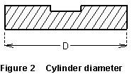
determine the mass of your hanging weight and the cylinder diameter D.
Carefully determine the diameter of the spindle without any string, and
again with a single layer of string wound uniformly around it. Take r
to be half the average of these two values.
(1) Carefully
determine the mass of your hanging weight and the cylinder diameter D.
Carefully determine the diameter of the spindle without any string, and
again with a single layer of string wound uniformly around it. Take r
to be half the average of these two values.
(2) Place the cylinder, pulley, etc., on the rotational dynamics apparatus. Be careful with these parts; any scratches on the cylinder surface will cause extra friction. Check to make sure that you have an air pressure sufficient to lift or �float' the cylinder. Check to see that the sensor is connected to the BIB box, and that the BIB box is connected to your computer.
(3) Turn on your computer, load up the program, or download it from Professor Moloney's home page. Make note of its PATH. Start MS-DOS on your computer. Access the PATH to the program, and execute the BBANGLW.EXE program.
NOTE: these instructions are guidlines only, please read the instructions on the screen! You must reset the program's parameters for the PASCO air wheel (or just air wheel):
press 7, then 6, then 6 again--to select air wheel
press 4, then 8, then 5 and select 1 channel
press 7, then 7, then 1 and select an appropriate number of data points
to capture
press 7, then 8, then 5 and set the data PATH to be able to properly store
your data
press 8, to prepare to take data.
When you get to the point of starting the first trial, wind up the string to a 'uniform single layer' depth on the spindle so that the hanging weight is just below the pulley. Release the cylinder from rest and, immediately after this, start the computer counting pulses by hitting the RETURN key. (Depend ing on your step in the program, you may need to hit RETURN again.) Make sure you take data for a long enough time to see clearly the descent of the mass. This program will collect data for the preset number of counts so the computer will take only the interval you set in.
After experimenting a little to get what you consider to be good data, store the data file (under a name you can remember), and be aware that the file will store the data in the form of the last graph you looked at. A recommendation is to store it as theta vs. time.
(4) Take whatever measurements you need to determine the distance the falling weight moves downward and the distance it travels back upward after rebounding at the bottom.
Or
(4) Count the number of marks, black and white, on the wheel, and make the number of samples taken match the total number of marks, then you have a number of 2 radians, or one circum ference, ( a known distance) to use as a "unit" of distance. (Make sure the actual distance matches the calculated distance, then match it to the presented number of radians on the last data pair recorded.)
(5) Repeat parts (3) and (4) with a flat metal plate attached to the cylinder. Measure the mass of the plate, and the lengths of its edges.
(6) Repeat parts (3) and (4) with a metal ring (hollow cylinder) added to the plate. Measure the mass of the ring, and its inside and outside diameters.
(1) Check to see that the computer is calculating angular position correctly by doing one sample calculation. For example, take the number of centimeters in a single circumference and set up a number of sampling data points so the mass "falls" "N" times the circumference then figure out the number of radians the cylinder has turned, and match this to the number on the graph of theta. Figure a way to calculate the angular velocity and the angular accelaration.
(2) Since the angular velocity increases linearly with time, the instantaneous angular velocity at the center of each interval should be the same as the average angular velocity over the interval. Use this fact to plot graphs of instantaneous angular velocity (down and up) versus time for each of the cases (3, 5, and 6) above. From the slopes of the, lines determine the two angular accelerations in each case.
The angular position is accelerating, so the angular velocity increases linearly with time. The program, BBANGLW.EXE includes a curve fitting module, active when a graph is displayed. Make use of the help instructions and curve fitting capability to "fit" an equation to the displayed data.
(CAUTION: Some thinking will be required to make use of a bare equation, and its calculated constants, to relate them to the theory.)
(3) How much uncertainty do you think there is in these angular acceleration values? If you want to do better than just an estimate, enter the data into a spreadsheet such as EXCEL, and do a least-squares fit to angular velocity vs. t.
(4) Adding Equations (4) and (5) gives
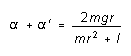
Use the angular accelerations you determined from Procedure (3) to determine
the moment of inertia of the disk. Use your error estimates for ![]() ,
,
![]() , m, and r and
propagation of errors to calculate the uncertainty in I in the string.
Show this calculation! From the analysis in the introduction, calculate
also
, m, and r and
propagation of errors to calculate the uncertainty in I in the string.
Show this calculation! From the analysis in the introduction, calculate
also ![]() and T,
with errors.
and T,
with errors.
(5) Repeat the calculations above for your data from parts 5 and 6 of the procedure, and determine the moments of inertia of the disk-plus-plate and the disk-plus-ring. Determine the moments of inertia of the plate and the ring, with errors. Also calculate their two moments of inertia from their respective masses and dimensions. Do your calculated and measured moments of inertia agree, within experimental error?
(6) In addition to accelerating the cylinder the falling weight also accelerates the pulley. In order to see if we are justified in ignoring this, calculate the approximate moment of inertia of this pulley from the following data, and compare with the cylinder's moment of inertia:
How would the presence of this pulley affect the angular acceleration of the cylinder? Is the effect appreciable?
Addition of Vectors: The Force Table
last update 6/98 - McGarvey/Moloney