A Precision, Student-Controlled Turntable
Physics educators have been very creative in using probes
to provide data input for Microcomputer-based (MBL) and calculator-based
(CBL) laboratory interfaces. These lab activities are clearly very productive,
and align well with the fundamental goal of engaging students in the effort
to understand the physical world. Many of us--and some of our students--are
genuinely thrilled with the graphs, the equations, and the new understands
we obtain from this type of activity.
Data input probes are not sufficient, however,
to satisfy all of our students. Most people who take introductory physics
courses (whether in high school or college) are hoping to use physics in
their careers as engineers, technicians, health professionals, or in other
applied fields. Their goal is not just to "understand" the equations
and graphs; they want to make things happen. Our courses ought to include
some laboratory experiences that appeal to these "practical"
students. Fortunately, the new generation of computer/calculator interfaces
(particularly the LabPro from Vernier) is making it far more convenient
to do action-oriented, applied labs. By using the output capabilities
of the new interfaces, we can make lab activities more exciting, more challenging,
and more practical for a larger number of our students.
Engineering-style control systems provide a rich and stimulating
set of opportunities for physics lab experiences. Traditional "applications"
in physics classes have too often consisted of a few plug-and-chug computations,
but control system activities go much further. Students derive a general
relationship linking inputs to outputs, and then they test to see for themselves
if the system actually works as they intended. Activities of this type
have long been popular as major projects for highly motivated students.
Low-cost educational technology is now making control system activities
practical as short-term lab experiences for all physics students.
The student-controlled turntable described here converts
the output of a calculator or computer into reality. Answers such as "81.4°"
or "tan-1(X/1.4)" are no longer just characters and graphs on
a screen--they are actual movements of a flashlight, a mirror or a lens.
The turntable can be constructed for less than $50, and can work with any
computer- or calculator-based interface that provides 4 digital output
lines. It can rotate to any specified direction with a precision of less
than 0.5°. When used with the CBL II or the LabPro, the turntable can
rotate at any specified angular velocity up to about 12 rev/min. Areas
of application include vectors, rotational kinematics and dynamics, optics,
electricity and magnetism, and others.
A Vector Activity
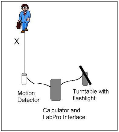 The
"FOLLOW" calculator program allows a student to investigate vectors,
first by using the keys of a calculator to manually control the direction
of a flashlight. In automatic mode, the program collects data from a motion
detector and stores the result as the variable "X". The program
then uses the function that a student has entered as "Y5" to
specify the direction. If students can apply the inverse trig functions
correctly, they can make the light follow a person walking towards the
detector. After dealing with the right-angle case, they can move on to
more complex arrangements. Many students find it very difficult to transfer
their paper-and-pencil understanding of trigonometry and vectors to the
physical situation shown here.
The
"FOLLOW" calculator program allows a student to investigate vectors,
first by using the keys of a calculator to manually control the direction
of a flashlight. In automatic mode, the program collects data from a motion
detector and stores the result as the variable "X". The program
then uses the function that a student has entered as "Y5" to
specify the direction. If students can apply the inverse trig functions
correctly, they can make the light follow a person walking towards the
detector. After dealing with the right-angle case, they can move on to
more complex arrangements. Many students find it very difficult to transfer
their paper-and-pencil understanding of trigonometry and vectors to the
physical situation shown here.
Other Activities
- A modification of the vector activity appropriate to
the study of geometric optics uses a fixed flashlight or laser, and mounts
a plane mirror on the turntable.
- For a more advanced challenge involving Snell's Law,
students can use a fixed laser aimed at a half-cylindrical lens on the
turntable.
A different type of student activity uses the turntable
motor itself as a focus. Unlike the split-ring commutator DC motors that
are familiar to most physics teachers, this is a "stepper motor"
that relies on external circuitry to shift current systematically from
one set of coils to the next. Such motors are very widely used in computer
disk drives, printers, and many other pieces of equipment that require
precise control of position. Using the manufacturer's specifications--plus
your understanding of torque and rotational inertia--can you determine
how to maximize the angular velocity of the motor?
- Electronics The output of a computer or calculator interface
provides low-power voltages intended to transmit logic, not energy. A convenient
way of amplifying those signals to power a small stepper motor is with
a "Darlington Array," such as the ULN2003A integrated circuit.
The 2003A consists of 7 channels (only 4 are used here), each of which
lets one low-power data line control one motor coil. When the signal line
is low (near 0 volts), the corresponding motor coil is isolated from ground.
When the signal goes high (near 5 volts) the motor coil is connected to
ground. The common wire for the unipolar stepper motor is connected to
a 12-volt source with a current capacity of at least 120 mA, and the motor
coils are connected in sequence to ground through the integrated circuit.
The 2003A needs no separate power source, but it is connected back to the
12-volt source through its pin 9 to aid in suppressing voltage spikes generated
by the motor coils. The 2003A allows very little current to flow when it
is not active, so an external switch is not necessary.
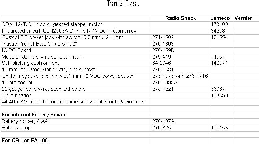
Parts List
- Radio
Shack Jameco
- GBM 12VDC unipolar geared stepper motor 173180
- Integrated circuit, ULN2003A DIP-16 NPN Darlington array
34278
- Coaxial DC power jack with switch, 5.5 mm x 2.1 mm 274-1582
151554
- Plastic Project Box, 5" x 2.5" x 2" 270-1803
- IC PC Board 276-159B
- Modular Jack, 6-wire surface mount 279-419 71951
- Self-sticking cushion feet 64-2346 142771
- 10 mm Insulated Stand Offs, with screws 276-1381
- Center-negative, 5.5 mm x 2.1 mm 12 VDC power adapter
273-1773 with 273-1716 16-pin socket 276-1998A
- 22 gauge, solid wire, assorted colors 278-1221 36767
- 5-pin header 103350
- #4-40 x 3/8" round head machine screws, plus nuts
& washers
- For internal battery power Battery holder,
- 8 AA 270-407A
- Battery snap 270-325 109153
- For CBL or EA-100 Digital output cord CBL-DIG (Vernier)
- For LabPro or CBL II Digital adapter CBL-P (Vern ier)
SUPPLIERS LISTED
- Jameco Electronics 1355 Shoreway Road, Belmont, CA 94022
www.jameco.com 1-800-837-6948
- Vernier Software 8565 S.W. Beaverton-Hillsdale Hwy.,
Portland, OR 97225 www.vernier.com (503) 297-5317
Step-by-Step Assembly Instructions Preparing the Project
Box
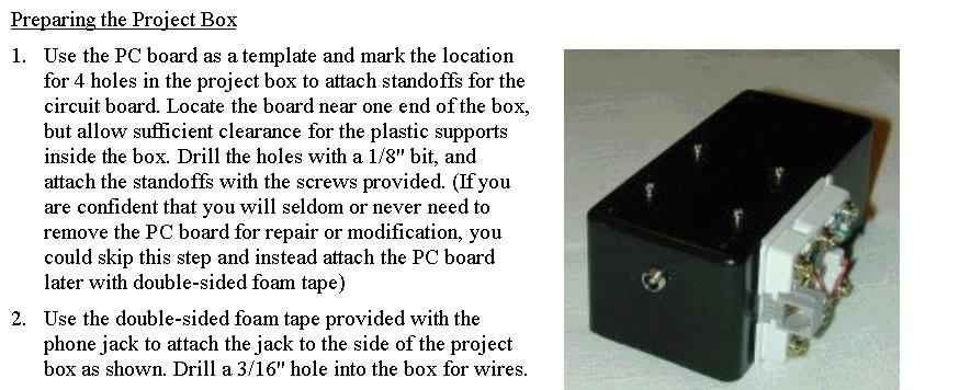
- 1. Use the PC board as a template and mark the location
for 4 holes in the project box to attach standoffs for the circuit board.
Locate the board near one end of the box, but allow sufficient clearance
for the plastic supports inside the box. Drill the holes with a 1/8"
bit, and attach the standoffs with the screws provided. (If you are confident
that you will seldom or never need to remove the PC board for repair or
modification, you could skip this step and instead attach the PC board
later with double-sided foam tape)
- 2. Use the double-sided foam tape provided with the phone
jack to attach the jack to the side of the project box as shown. Drill
a 3/16" hole into the box for wires.
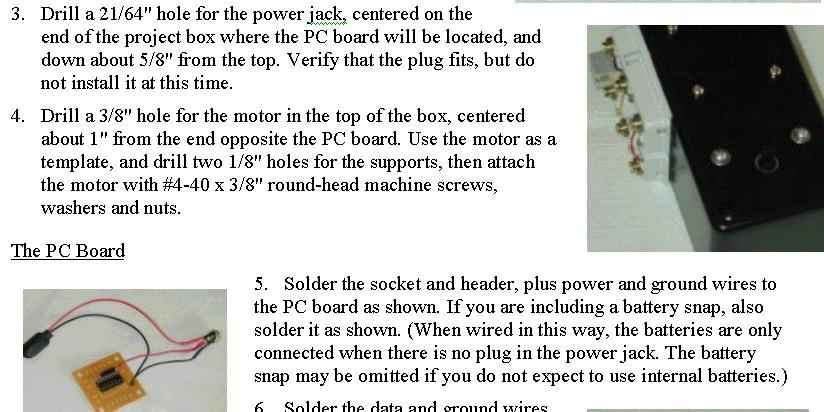
- 3. Drill a 21/64" hole for the power jack, centered
on the end of the project box where the PC board will be located, and down
about 5/8" from the top. Verify that the plug fits, but do not install
it at this time.
- 4. Drill a 3/8" hole for the motor in the top of
the box, centered about 1" from the end opposite the PC board. Use
the motor as a template, and drill two 1/8" holes for the supports,
then attach the motor with #4-40 x 3/8" round-head machine screws,
washers and nuts. The PC Board
- 5. Solder the socket and header, plus power and ground
wires to the PC board as shown. If you are including a battery snap, also
solder it as shown. (When wired in this way, the batteries are only connected
when there is no plug in the power jack. The battery snap may be omitted
if you do not expect to use internal batteries.)
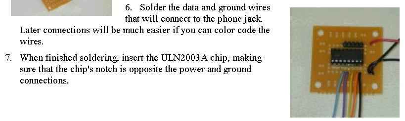
- 6. Solder the data and ground wires that will connect
to the phone jack. Later connections will be much easier if you can color
code the wires.
- 7. When finished soldering, insert the ULN2003A chip,
making sure that the chip's notch is opposite the power and ground connections.
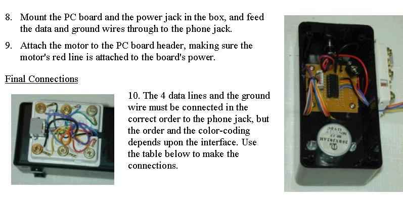
- 8. Mount the PC board and the power jack in the box,
and feed the data and ground wires through to the phone jack.
- 9. Attach the motor to the PC board header, making sure
the motor's red line is attached to the board's power. Final Connections
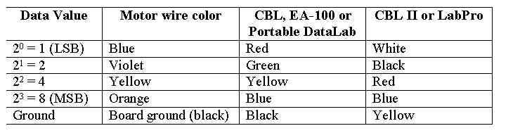
- 10. The 4 data lines and the ground wire must be connected
in the correct order to the phone jack, but the order and the color-coding
depends upon the interface. Use the table below to make the connections.
- 11. Add the battery holder, if desired, fasten the bottom
to the box and attach four feet.
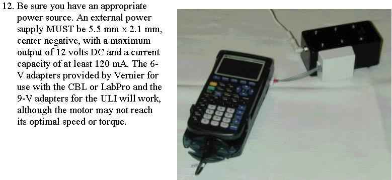
- 12. Be sure you have an appropriate power source. An
external power supply MUST be 5.5 mm x 2.1 mm, center negative, with a
maximum output of 12 volts DC and a current capacity of at least 120 mA.
The 6-V adapters provided by Vernier for use with the CBL or LabPro and
the 9-V adapters for the ULI will work, although the motor may not reach
its optimal speed or torque.
Two versions of the program listing are given below.
There are some difficulties with a few of the characters, and one should
check with the author for the correct version. (One version was screen
captured, and the other was from copying and pasting.)
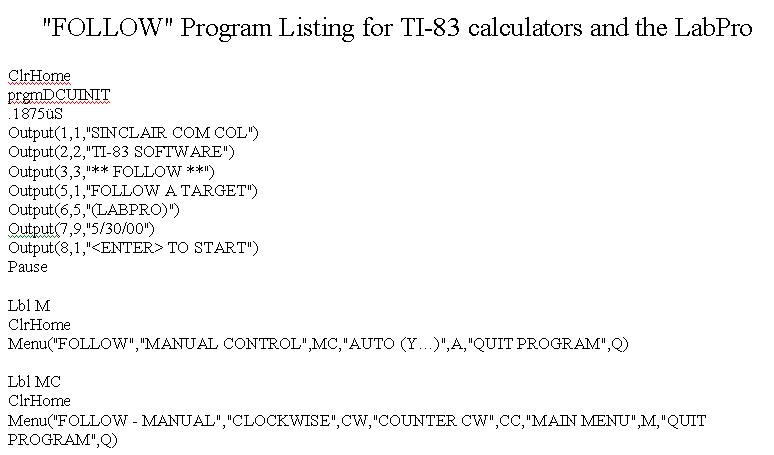


"FOLLOW" Program Listing for TI-83 calculators
and the LabPro
- ClrHome
- prgmDCUINIT
- .1875üS Output(1,1,"SINCLAIR COM COL")
- Output(2,2,"TI-83 SOFTWARE")
- Output(3,3,"** FOLLOW **")
- Output(5,1,"FOLLOW A TARGET")
- Output(6,5,"(LABPRO)")
- Output(7,9,"5/30/00")
- Output(8,1,"<ENTER> TO START") Pause
- Lbl M ClrHome Menu("FOLLOW","MANUAL CONTROL",MC,"AUTO
(Y�)",A,"QUIT PROGRAM",Q)
- Lbl MC ClrHome Menu("FOLLOW - MANUAL","CLOCKWISE",CW,"COUNTER
CW",CC,"MAIN MENU",M,"QUIT PROGRAM",Q)
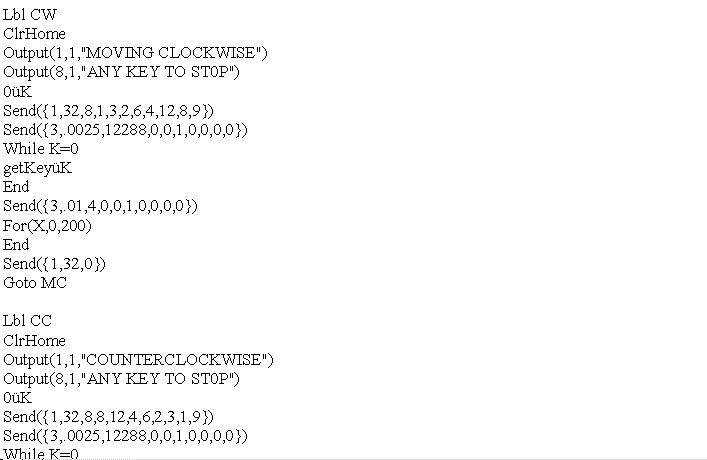
- Lbl CW ClrHome Output(1,1,"MOVING CLOCKWISE")
Output(8,1,"ANY KEY TO ST0P") 0üK Send({1,32,8,1,3,2,6,4,12,8,9})
Send({3,.0025,12288,0,0,1,0,0,0,0}) While K=0 getKeyüK End Send({3,.01,4,0,0,1,0,0,0,0})
For(X,0,200) End Send({1,32,0}) Goto MC
- Lbl CC ClrHome Output(1,1,"COUNTERCLOCKWISE")
Output(8,1,"ANY KEY TO ST0P") 0üK Send({1,32,8,8,12,4,6,2,3,1,9})
Send({3,.0025,12288,0,0,1,0,0,0,0}) While K=0 getKeyüK End Send({3,.01,4,0,0,1,0,0,0,0})
For(X,0,200) End Send({1,32,0}) Goto MC
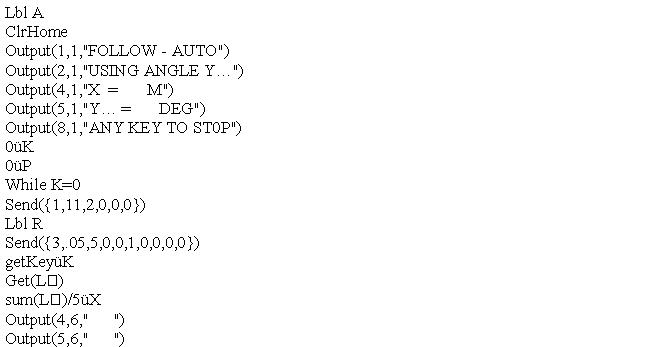
- Lbl A ClrHome
- Output(1,1,"FOLLOW - AUTO") Output(2,1,"USING
ANGLE Y�")
- Output(4,1,"X = M")
- Output(5,1,"Y� = DEG")
- Output(8,1,"ANY KEY TO ST0P") 0üK 0üP
While K=0 Send({1,11,2,0,0,0}) Lbl R Send({3,.05,5,0,0,1,0,0,0,0}) getKeyüK
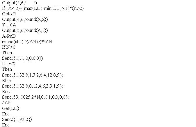
Get(L�) sum(L�)/5üX Output(4,6," ") Output(5,6," ")
If (X<.2)+(max(L�)-min(L�)>.1)*(K>0) Goto R Output(4,6,round(X,2))
Y�üA Output(5,6,round(A,1)) A-PüD round(abs(D)/S/4,0)*4üN
If N>0 Then Send({1,11,0,0,0,0}) If D<0 Then Send({1,32,8,1,3,2,6,4,12,8,9})
Else Send({1,32,8,8,12,4,6,2,3,1,9}) End Send({3,.0025,2*N,0,0,1,0,0,0,0})
AüP Get(L�) End Send({1,32,0}) End Send({1,11,0,0,0,0}) Goto M
- Lbl Q ClrHome Send({0}) DelVar A DelVar D DelVar K DelVar
N DelVar P DelVar S DelVar L�