Apparatus Title: Modernized Air Column Resonance Apparatus: Design and Performance
Abstract
A homemade modernized version of an air column resonance apparatus for determining the speed of sound in air is described and its performance characteristics are demonstrated. The results are highly reproducible, very precise and sensitive to air temperature.
Sketch of the apparatus:

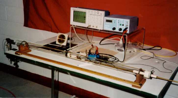
Experimental setup: The microphone used as speaker is clamped to the table on the left side and faces the end of the resonance tube. The scope is shown on the left of the function generator.
Description MODERNIZED AIR COLUMN RESONANCE APPARATUS: Design and Performance
INTRODUCTION
The traditional air column resonance apparatus, which uses water to vary the length of the column, has been in use to determine the speed of sound in air for over one hundred years[1]. The experiment is easy to perform and it produces a loud audible sound at resonance[2]. It provides an excellent demonstration to illustrate acoustic resonance and gives fairly good results. It is relatively inexpensive and requires low maintenance
However, the commercially available resonance tube has several drawbacks. They include: qualitative and imprecise determination of the resonance position, water overflow from the water reservoir causing slippery spots on a waxed floor - a potential hazard, impurity deposits and corrosion of the metal parts restrict the flow of water, to name a few. Another version of the commercially available resonance tube with washer as a piston produces broad resonance, which makes the precise location of the resonance peak difficult and frustrating.
A homemade, high-tech air-column resonance apparatus, as described here, not only alleviates these problems but also produces results for the speed of sound with such high precision that allows the study of its dependence on air temperature. The new design uses a small speaker as a sound source and a tie-clip microphone as a detector for resonance. It differs fundamentally from the commercially available air-column resonance apparatus[3a]. The key difference of the new design is that the movable piston is made practically airtight to the acoustic pressure, which gives rise to narrow resonance peaks making the results precise and highly reproducible. Its performance characteristics are discussed, including the effect of air temperature on the speed of sound, the end correction, and factors affecting the sharpness of resonance. In addition, the new design provides an advanced undergraduate sound experiment for the hearing impaired and others.
DESIGN AND OPERATION
The setup reported in this paper is shown in figure 1. The resonance tube, seen in the front of the setup, consists of a graduated glass -tube of 3.62-cm internal diameter and ~110 cm in length. The movable 'closed end' of the tube is made of a metal washer of 3.5 cm in diameter. A leather washer, similar to the one used in a bicycle air pump, is placed immediately behind the metal washer to make this piston-assembly almost air tight to the small acoustic pressure, but allows it to move smoothly within the tube. The lip of the leather washer is just about flush with the face of the metal washer. The two washers are screwed slightly off center and perpendicular to the end of a 115-cm long metal rod of ~ 6mm diameter.
A tie clip microphone (RadioShack, 33-3013)[4] is installed at the center of the piston assembly with its screen flush with the face of the metal washer. The metal rod as well as the microphone leads pass through a rubber stopper at the remote end of the tube. The rod moves the piston up or down providing an air column of variable length. An old microphone (1.5-cm in dia.) was used as a speaker and driven sinusoidally with a digital function generator/amplifier (PASCO, PI- 9587C)[3b] to serve as a source of sound waves.
The microphone output is fed directly into a digital oscilloscope (Tektronix, TDS-210)[5]. The signal, averaged over 128 samples, is displayed and its peak-to-peak voltage is read directly from the oscilloscope. Plot of the signal versus the position of the piston yields a response curve.
The experiment was performed, for the most part, in the basement of a house where the temperature was very stable within less than ± 0.1 oC during any single set of observations. The humidity was held at (57 ±3) % with a dehumidifier. The observations were taken at 500 Hz except those for the end correction. The end correction was determined by plotting the air column length at first resonance versus the inverse of frequency. The frequencies ranged, from 350 Hz to 700 Hz at 50 Hz interval.
To study the effect of temperature, the experiment was conducted on a hot summer day. The data were collected before noon inside the house by cooling it to the lowest achievable temperature of 19.4 oC. For the higher temperature, data were taken at 28.6 oC in the afternoon in the garage with the door closed to minimize temperature fluctuations.
RESULTS AND DISCUSSION
Reproducibility
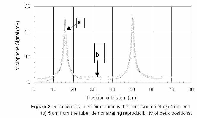
Figures 2a and 2b show typical resonance plots of the first two resonance peaks. These plots depict the data taken three days apart, with the speaker placed at 4 cm (fig. 2a) and 5 cm (fig. 2b) from the end of the tube, at 23.7 ± 0.1°C and 23.8. ± 0.1°C, respectively
The two plots show no discernable difference in the positions of the resonance peaks even when the sound source is shifted by 1 cm. The shape of the response curves and the peak positions are almost identical. The relative peak heights are some what altered. It should be pointed out that these data are individual runs and not averaged over several trials. Also, an uncertainty of ± 0.01 cm (estimated) is inherent in the process of measurement. This uncertainty arises because of the parallax between the front edge of the piston and the scale markings on the outside of the tube.
The overlapping of the peak positions demonstrates that the results are highly reproducible and insensitive to the position of the speaker. The sharpness of the resonance peaks shows a high degree of resolution and accuracy achievable in the determination of the speed of sound. The speed of sound (V) is determined by using the standard formula
V = f l = 2 f DL (1),
where f stands for the wave frequency, l its wavelength, and DL = L2 - L1. L1 and L2 are the first and the second resonance peak-positions from the end of the tube. The speed is calculated to be 343.75 m/s, averaged over the two data sets. Though this value turns out to be very close to the expected value of 343.87 m/s, it requires further study to make such a definitive claim. Our best estimate of the uncertainty in the speed is less than ± 1 m/s. After making some improvements and averaging the results over several trials, the uncertainty can be significantly reduced. Here, we are demonstrating the high precision achievable with an inexpensive setup. (The expected value used in above comparison is based on the speed of sound in free dry air[6] and corrected for the effect of the tube size[7]. The effect of humidity is not considered in this comparison. It may add up to 0.2 %[6]).
Dependence of Speed on Air Temperature
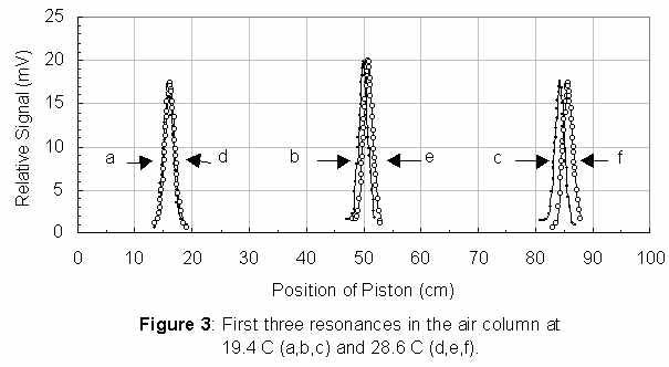
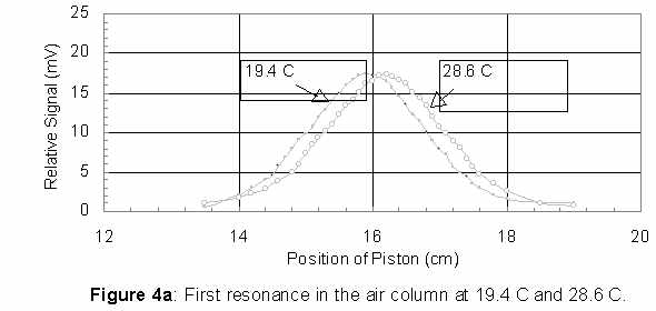
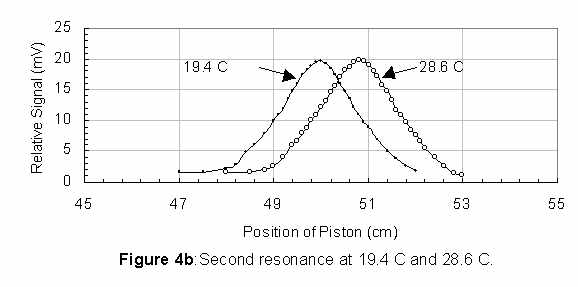
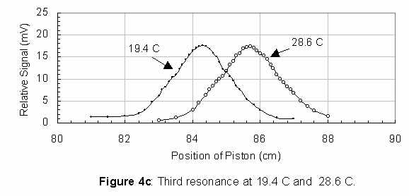
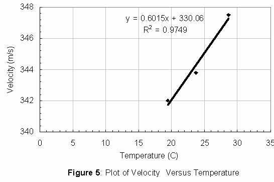
The dependence of the speed of sound on air temperature[2,8] and hence the resonance positions are demonstrated by plots in figures 3 and 4. Figures 3(a, b, c) and 3(d, e, f) show the first three resonance curves observed at 19.4 ±0.2°C and 28.6 ± 0.2 °C, respectively. The same three resonance pairs are displayed in figures 4a, 4b, and 4c on an expanded scale. The peaks in all the three cases are clearly well resolved. Figure 5 shows a plot of the speed versus temperature and the regression line. The temperature coefficient as given by the slope of the line is 0.6 m/s/°C that is unbelievably close to the standard value of 0.6 m/s/°C[2]. However, it requires additional data at several temperatures in a regulated environment to draw such a conclusion. The intercept of the best-fit line gives the speed of sound as 330.1 m/s at 0 °C, which is within 0.1% of the standard value of 329.8m/s, after correcting for the tube size2,7.
It should be noted that the speed of sound values for the two outer points in figure 5 were calculated by taking into account the first and the third resonance positions at the two temperatures. This improves the accuracy by a factor of two as compared to the results based on the first and the second resonance positions. The middle point corresponds to the average of the speeds from the two data sets of figure 2.
End Correction
The end correction (Dl) for an un-flanged tube of radius r and for low frequency waves is given by[9]
Dl = 0.61 r (2).
If L1 is the length of the air column at first resonance then[10]
L1 = (V/4) 1/f - Dl. (3)
The plot of L1 versus 1/f should produce a straight line. Its slope and the intercept on the length-axis give the speed of sound (V) and the end correction Dl, respectively.
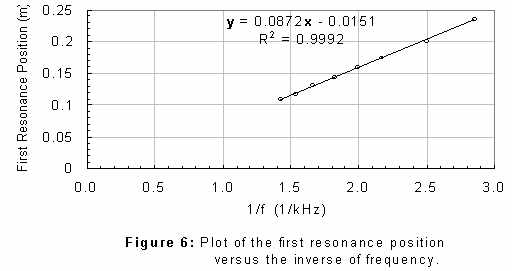
Figure 6 shows such a plot. In this case, the data were collected over an extended period of time during which the temperature varied from 23.8 to 24.6 °C. However, the majority of the points lie within a temperature range of 24.3 ± 0. 3 °C. The speed calculated from the slope is 348.8 m/s, which compares well with the expected value of 344.6 m/s with a difference of 1.2%. This high deviation is expected because all data were not collected at a constant temperature and a small error in the value of the slope multiplies the error in the speed by four.
The intercept gives the end correction to be 1.5 cm whereas its theoretical value is 1.1 cm. It should be pointed out that our value is expected to be slightly higher due to the unevenness of the end of the resonance tube. The zero of the scale printed on the tube coincides with the apex of the uneven end. The length of the air column is effectively smaller by a fraction of a millimeter (estimated to be ~ 0.3mm) than recorded. This may introduces up to an equal increase in the experimental value of the end correction. Considering this limitation, the experimental value is in good agreement with the theory.
Sharpness of Resonance
The dependence of the resonance width was investigated with pistons of several diameters. A small speaker (5 cm in diameter) was used instead of the microphone-turned-speaker (used in all the previous observations), because higher power was needed to get meaningful signals with pistons of smaller diameters. It was placed at ~ 8cm from the end of the tube. All observations were taken at a constant amplitude setting of the function generator.
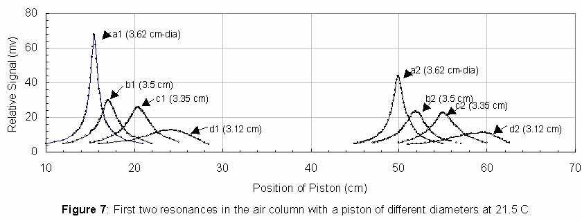
Figure 7 shows the first and the second resonance peaks at 500 Hz and 21.5 °C ± 0.5 °C with pistons of different diameters: 3.62 cm- the leak tight piston (a1, a2), 3.50 cm (b1, b2), 3.35 cm (c1, c2), and 3.12 cm (d1, d2). It shows that the resonance curves become increasingly flat and the signal height decreases as the piston diameter decreases. It also shows a sharp drop in the height of the resonance peak when the diameter changes from 3.62 cm to 3.50 cm. Also the positions of the resonance peaks shift significantly toward larger distances from the end of the tube as the piston diameter decreases. However, the distance between the first and the second resonance positions remains the same and equal to one half-wavelength. As the resonance width becomes larger so does the uncertainty in determining the position of the resonance.
These observations clearly demonstrate why it is difficult to locate the position of the resonance in a commercially available resonance tube with a flat washer as a piston of smaller diameter than that of the tube. In some of the commercial tubes, the diameter of the piston in comparison to that of the tube is much smaller than those we have tried. This makes it even more difficult to locate the position of the resonance by listening.
It is also clear that the concept of the end correction, as it is known, is applicable only when the closed end is really closed, i.e. it is leak tight.
CONCLUSION A homemade modernized air column resonance apparatus has been described and its performance characteristics have been discussed in detail. The position of resonance is determined quantitatively. The results are highly reproducible and are much more precise than those obtainable with the traditional qualitative method of locating the resonance position by listening. The precision is high enough to study the effect of air temperature on the speed of sound. The arrangement described above can be easily adapted for use as a closed tube to determine the speed of sound in different gases.
It has been demonstrated that the sharpness of resonance depends on how tight fitting the piston is. The sharpest resonance is obtained with a leak-tight piston with its face perpendicular to the tube axis. The deviation from perpendicularity may cause different parts of the piston to be in resonance at its different positions. (We have observed some evidence but have not fully investigated it).
The modernized version of the air column setup is not very expensive. It is rather inexpensive considering how much more physics can be learned when compared to the traditional resonance apparatus. The piston can also be made with a rubber stopper or with a closely fitting PVC tube or a coupling, which can be plugged, with a rubber stopper.
The resonance apparatus discussed above can serve as a high school or an undergraduate research project. Most importantly, it provides an advanced undergraduate sound experiment for the hearing impaired.
REFERENCES
Apparatus Title: Air-Column Resonance Apparatus Re-Designed
Abstract
A re-designed air-column resonance apparatus is described. It does away with water or the long rod. A specially designed piston is magnetically moved up or down the tube to provide an air column of variable length. Sample data are provided to demonstrate its performance. Enhancement possibilities are summarized.
Equipment required to construct apparatus:
Item Source/Store Part Number Cost United States Plastic Corp.:
Sketch of the apparatus (see below)
Description:
Introduction A re-designed air-column resonance apparatus is discussed, which does away with water or the long rod. A specially designed piston is magnetically moved up or down the tube to provide an air column of variable length. Sample data are provided to demonstrate its performance. Enhancement possibilities are summarized.
Design of the Resonance Apparatus.
 The
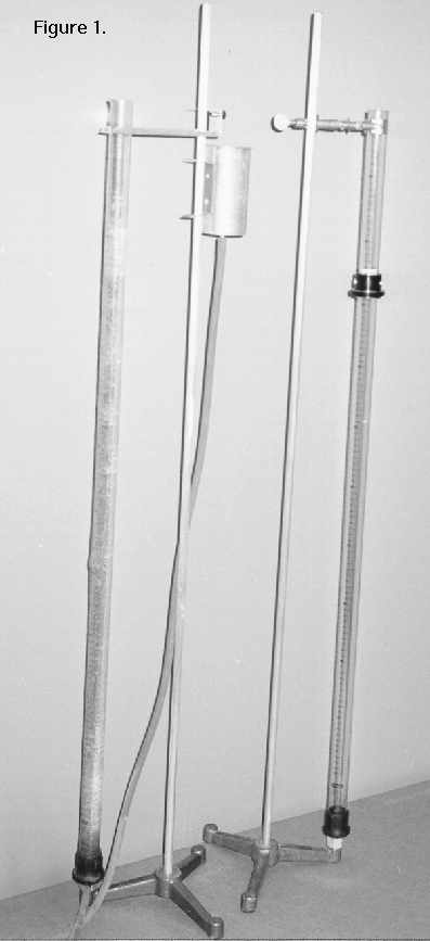
design described below is very simple. Figure 1 shows the newly designed
air-column resonance apparatus along with the traditional one with its
water reservoir. The redesigned tube can be operated in the horizontal
or the vertical position. A clear plastic or glass tube with a short piston
forms the resonance apparatus. Plastic tubes of various sizes are commercially
available1, but we salvaged it from a leaky commercial resonance tube (of
2.85-cm inner diameter and 3.15 cm outer diameter). The tube is clamped
to its original tripod stand. The details of the magnetically movable piston
are discussed below.
Magnetically Movable Piston The requirements for the design of the magnetically movable piston assembly are a closely fitting piston that moves smoothly inside the resonance tube and a collar that glides around it and houses two neodymium magnets. To do it without machining, one can take advantage of the multitude of PVC and other plumbing supplies. In the case described here, a PVC coupling of ½-inch nominal size and of 2.8 cm O. D. was a perfect match as a piston for our tube. The coupling is cut into two halves. A ring band (~0.75 cm wide) is cut out of a steel tube of outer diameter very close to that of the PVC coupling. In our case it is 2.7 cm. (The steel tube is of ¾ inch nominal size). A 3-cm long piece of ½ inch PVC tube is inserted into the steel band. The two halves of the coupling are cemented together with the PVC tube thereby sandwiching the steel band. The coupling is closed at one end with a suitable rubber stopper. The stopper is flushed even with the rim of the coupling. This forms the piston as shown in figure 2. Figure 2 also shows the collar and two neodymium magnets.
Another plumbing coupling (of 3.2 cm I.D.) is cut ~4 cm in length to make the collar. Two holes are drilled, diametrically opposite, at about the middle of the collar, to house the magnets (1.25 cm in diameter). The piston is installed inside the resonance tube and the collar with two neodymium magnets around it. The magnets latch on to the steel band and hold the piston in position as well as drag it when the collar is moved along the tube. Complete assembly is shown in figure 3. The collar on the tube shown in figure 1 is made of anodized aluminum, which was available in the laboratory and happened to fit.
It should be noted that a steel pin (~0.75 cm in diameter) can also be used instead of the steel band. The pin may be cut from a bolt and installed diagonally at about the middle of the piston. The opposite ends of the pin are filed even with the surface of the coupling.
Results and Discussion The performance of the redesigned tube is the same as that of the traditional resonance tube with the water column. A vibrating tuning fork of known frequency is held at the open end of the resonance tube. First and the second resonance positions are located. Difference between their positions (L1, L2) determines the wavelength [l = 2 (L2 - L1)]. The procedure is repeated a few times to arrive at an average value of the wavelength. The speed of sound averaged over data taken with five tuning forks is found to be 342.5± 4.3 m/s at 21.5 °C. The expected value is close to 344.5 m/s. No effort is made to determine the accuracy of the frequency of the tuning forks.
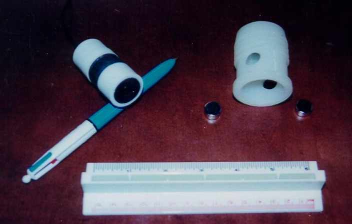
Figure 2.
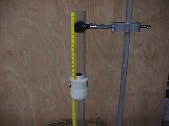
Figure 3.
Enhancement Possibilities
The capabilities of the new design can be further enhanced by using a small speaker as a source of sound waves and a tie-clip microphone installed at the center of the piston as a detector for the sound level. Plot of the microphone signal versus position of the piston shows sharp resonance peaks, which give highly reproducible results with much greater precision. The simplicity of the design makes it easily adaptable to study the speed of sound in different gases and its temperature dependence. Also, this enhanced set-up provides an advanced level undergraduate sound experiment even for the hearing impaired. However, this enhancement is not within the $65 limit.
REFERENCES
Apparatus Title: Air Column Resonance Apparatus Re-Engineered With Contemporary Technologies
Abstract
A re-engineered resonance apparatus is discussed. It uses two neodymium magnets to move a piston to vary the length of the air column, a mini speaker for sound waves and a tie-clip microphone to detect the resonance peaks. It produces sharp peaks resulting in precise values for speed of sound.
Sketch of the apparatus:
It is shown as figure 1 given under description. A complete description of the apparatus is desirable, detailed enough that others can duplicate the apparatus. This description (anonymous) will be available to the judges of the apparatus. Samples of student reports (anonymous) may also help the judges to recognize the merits of this apparatus. Description AIR-COLUMN RESONANCE APPARATUS RE-ENGINEERED With Contemporary Technologies
ABSTRACT A re-engineered resonance apparatus is discussed. It uses two neodymium magnets to move a piston to vary the length of the air column, a mini speaker for sound waves and a tie-clip microphone to detect the resonance peaks. It produces sharp peaks resulting in precise values for speed of sound.
INRODUCTION A re-engineered air-column resonance apparatus is discussed which does away with water column or the long rod. A specially designed piston is magnetically moved up or down the tube to provide an air column of variable length. A small speaker is used as a source of sound waves and a tie-clip microphone is installed at the center of the piston to detect the sound level. Plot of the microphone signal versus the position of the piston produces sharp resonance peaks. The simplicity of the design makes it easily adaptable to study the speed of sound in different gases. Also, this set-up provides an advanced level undergraduate sound experiment even for the hearing impaired.
DESIGN OF THE RESONANCE APPARATUS A clear plastic or glass tube with a short and magnetically movable piston forms the basic resonance apparatus. Plastic tubes of various sizes are commercially available[1], but we salvaged it from a leaky commercial resonance tube (of 2.85-cm inner diameter ad 3.15 outer diameter). The details of the resonance tube closed at both ends are described for its use to determine the speed of sound in different gases. However, illustrative results are given only for the speed of sound in air.
Magnetically Movable Piston
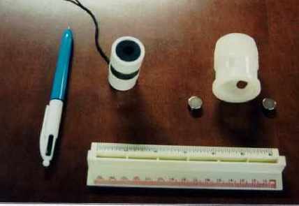
The requirements for the design of the magnetically movable piston assembly are a closely fitting piston that moves smoothly inside the resonance tube, and a collar to glide around it and house two neodymium magnets. To do it without machining, one can take advantage of the multitude of PVC and other plumbing supplies. In the case described here, a PVC coupling of ½-inch nominal size and of 2.8 cm O. D. is perfect for a piston in our case. The coupling is cut into two halves. A ring band (~0.75 cm wide) is cut out of a steel tube of diameter ~2.7 cm. (The steel tube is of ¾ inch nominal size). A 3-cm long piece of ½ inch PVC tube is inserted into the steel band. The two halves of the coupling are cemented together with the PVC tube thereby sandwiching the steel band. The coupling is closed at one end with a suitable size rubber stopper flushed even with the rim of the coupling. A tie-clip microphone (Radio Shack Cat. No. 33-3013)[2] is installed at the center of the rubber stopper flush with its surface. This forms the piston a shown in figure 1. Figure 1 also shows the collar and two neodymium magnets[3] as discussed later.
Another plumbing T- coupling (of 3.2 cm I.D.) is cut ~4 cm in length to make the collar. Two holes are drilled, diametrically opposite, at about the middle of the collar to house the magnets (1.25 cm in diameter). The piston is installed inside the resonance tube and the collar with two neodymium magnets around it. The magnets latch on to the steel band and hold the piston in position as well as drag it when the collar is moved along the tube.
Sound Source and the Detector A unidirectional dynamic microphone of a cylindrical shape (1.5 cm in diameter) is used as a speaker. Its small size and cylindrical shape makes it convenient to insert through a rubber cap which closes one end of the resonance tube. It is driven sinusoidally with a digital function generator/amplifier (PASCO, PI-9587C) [4] to serve as a source of sound waves. The tie-clip microphone, installed at the center of the piston, faces the speaker and serves as a detector for acoustic pressure.
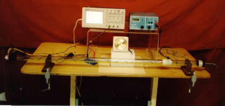
Figure 2.
The remote end of the tube is closed with another cap. Feed-throughs are install in the cap to take the microphone signal out. Gas inlet and outlet are installed at opposite ends of the tube to allow the study the speed of sound in different gases. The complete setup as laid out on the table is shown in figure 2 (at the right).
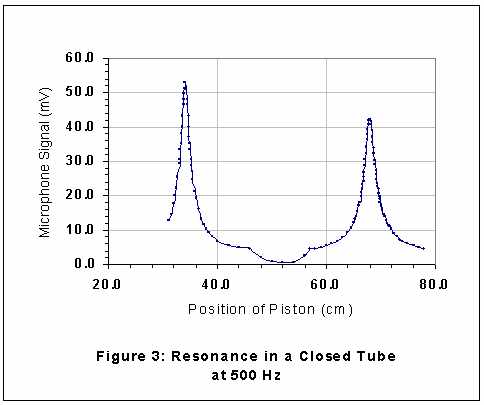
The speaker is operated at 500 Hz. The microphone signal is fed into a digital real-time oscilloscope (Tektronix model TDS 210)[5]. The signal is averaged over 128 samples and displayed. Its peak-to-peak voltage is read and the position of the piston is noted. A plot of the signal versus the position of the piston gives a resonance response curve. RESULTS AND DISCUSSION The data were collected at 16.0 °C with air in the resonance tube. Figure 3 shows a typical response curve. Resonance peaks are sharp, well defined and are separated by one half-wavelength. The speed of sound calculated from this data is found to be 339.0 m/s, which is within 0.03 % of the expected value 338.9 m/s, after correcting for the size of the tube[6,7]. The effect humidity[6] is not considered I this comparison which may add ~0.2 % to the expected value. If humidity is taken into account, the experimental value is still within 0.2%. Plots of this type are highly reproducible with response peaks within 0.5mm in the worst case. This may causes an error of no more than 2 mm in the determination of the wavelength. This amounts to a maximum error of less than 0.3 % in the determination of the speed of sound. The results given above clearly demonstrate the high degree of precision obtainable with the re-engineered resonance apparatus. Moreover, the location of the resonance peaks is determined quantitatively rather than qualitatively by listening. Instead of air, one can use any other gas. Also, this setup can be used by anyone even with hearing impairment.
REFERENCES